CFD – Distribution Vessels
Posted on May 16, 2023 Computational Fluid Dynamics Mixing Multiphase Flows

This post was originally published in two parts which have been combined below.
Part 1
A pump box is a type of distribution vessel that receives separate streams, with varying material properties and compositions, and endeavors to provide a well-mixed flow of identical composition to multiple outlets. These vessels may be subject to diverse flow scenarios such as nominal/upset operating conditions, different fill levels, and varying density or particle size distribution at the inlets. Some of these scenarios can result in undesirable issues like excessive wear on vessel internals, or air entrainment—which should be avoided during the mixing process.
For instance, if each stream contains a wide particle size distribution, there is a high probability that coarse solids will accumulate on one side of the vessel, creating a dead zone that can cause issues for pumping requirements and result in variability of outlet properties during operation. It is crucial that pump box designs are robust enough to address mixing requirements for various process conditions. If a particular design does not provide adequate mixing at the outlets or results in an unacceptable amount of air entrainment, computational fluid dynamics (CFD) simulations can validate the undesirable performance, and then design modifications can be tested to determine if they improve the vessel’s performance.
In our next post, simulations of a pump box in its original configuration and with modified inlets will be presented to illustrate the effectiveness of CFD for the analysis of distribution vessels.
Part 2
In the previous post, the challenges associated with distribution vessels were identified and CFD was suggested as a useful tool to analyze and improve their performance.
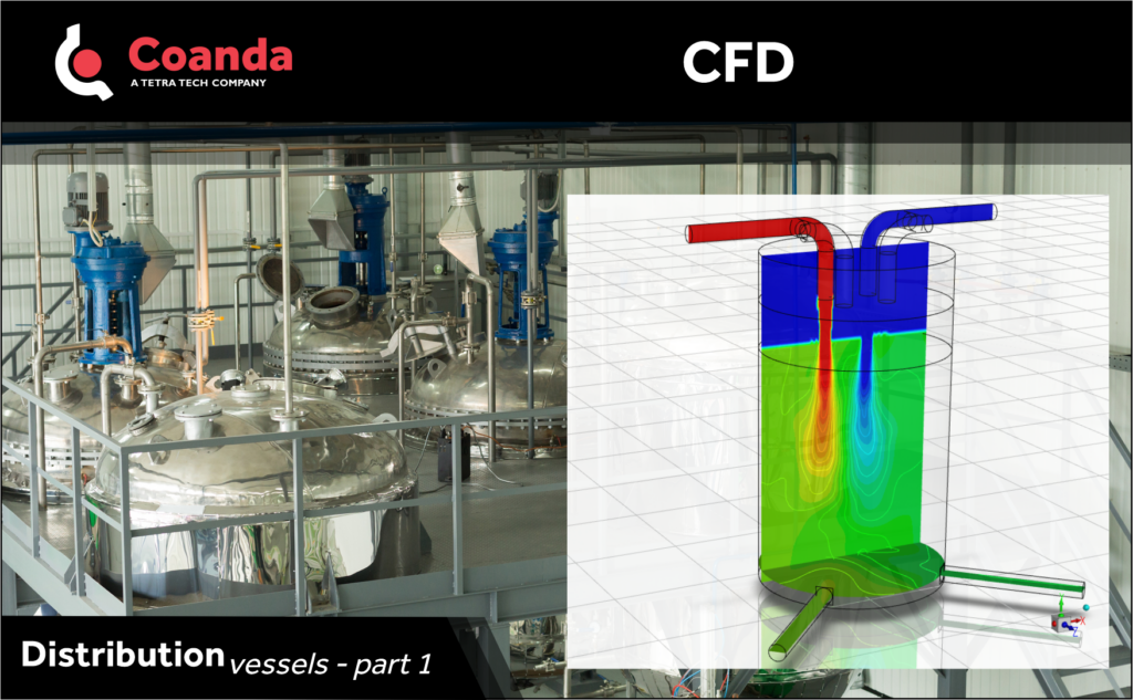
The animations illustrate simulations of the mixing process in a pump box consisting of a cylindrical vessel with two inlet streams and two outlet streams; the inlets convey a Newtonian fluid at an inlet pipe Reynolds number of 105. Note that the inlet pipes terminate approximately three inlet pipe diameters above the fill level of the vessel. The free surface of the liquid, colored by velocity magnitude contours, is presented for two cases: (left) the original design with two streams and two outlets, and (right) the modified design where each inlet stream is split into two streams before it is introduced to the vessel, resulting in four streams but with the same outlet streams. For presentation purposes, the original design also shows the additional pipes proposed for the modified design. Both simulations exhibit some level of air entrainment into the vessel pool due to the plunging jets, with somewhat higher air entrainment in the modified vessel.
Contours of mass fraction on the central plane through the vessel are also shown in the figures. In the original design, there is a higher tendency for stream 1 (the pipe on the right) to exit through outlet 1 (the outlet on the right); the flow from inlet 1 accounts for approximately 60% of the flow in outlet 1. In the modified design, there is improved mixing between the streams within the vessel, such that each inlet stream contributes approximately 50% of the flow to each outlet.