CFD Modeling of a Pulp Mill Headbox
Posted on November 16, 2022 Computational Fluid Dynamics Pulp & Paper

This post was originally published in two parts which have been combined below.
Part 1
CFD modeling of the fluid flow through a hydraulic headbox
A paper machine headbox is one of the most important parts in the paper making process. The main purpose of the headbox is to convert a fiber suspension flow in a round pipe into a uniform flat jet several meters wide that will fall on wire mesh, or the wire as it is known, to start the dewatering process.
The evolution of headbox design is motivated by the need to increase productivity, which requires higher operational speed. Design has progressed from open air headboxes with agitating rolls to the more modern high speed hydraulic type. Hydraulic headboxes do not rely on air pressure to equalize the flow, but rather utilize hydraulic pressure that creates a high flow velocity.
Because full-scale experiments can be very costly, there is substantial interest in CFD modeling that can provide the required information regarding the effects that the various design elements would have on the flow.
As it is generally believed that uniform flow at the exit of the headbox, or slice, produces good quality paper, researchers have concentrated on the analysis of the flow through the headbox, with the aim of obtaining uniform exit flow. The headbox output can be controlled by adjusting the recirculation ratio, changing the slice opening height and changing the amount of edge flow.
In our next post we’ll cover the approach we used to develop a suitable CFD model.
Part 2
In our previous post, we introduced headboxes as an important component in the papermaking process and the use of CFD modeling thereof to optimize performance.
The main challenge of headbox modeling is the presence of a large number of tubes (numbering in the thousands) connecting the main manifold (header) to the end section. To provide sufficient information for the headbox flow in a practical way, original simplification methods had to be developed. We introduced the use of bilinear approximations for some of the tubes, instead of solving a full system of flow equations inside each tube. This procedure effectively reduces the number of tubes that need to be explicitly resolved. In this approach, tubes in areas that have relatively constant gradients of flow properties between adjacent tubes (usually the central part of the headbox) are replaced with inlet and outlet boundary conditions in the corresponding headbox segments that they connect, as shown in the attached figure. To confirm that this method provides sufficiently accurate results, a smaller headbox case with reduced width, and therefore reduced number of tubes, was solved with some tubes replaced as described above and the solution was compared to the case with all tubes present.
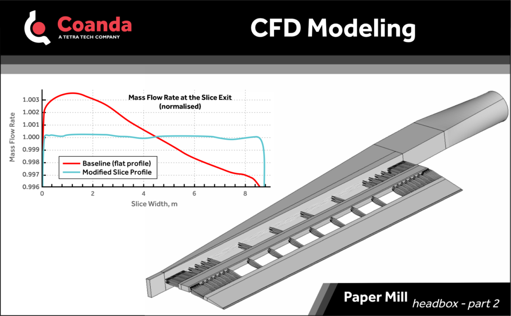
The application of the developed CFD model to a hydraulic headbox provides insights to the flow and allows us to investigate the effectiveness of various operational and design parameters to control the output flow. Operational control parameters such as recirculation rate, edge flow, and slice profile, have rather limited albeit an important effect on the exit flow. At the same time, as the graph illustrates, modification of the header manifold has a potential to dramatically improve the uniformity of the flow at the exit of the slice.