Atmospheric Dispersion Modelling
Posted on February 16, 2017 Environmental Science Physical Modeling
Atmospheric dispersion is the process by which airborne materials are transported and mixed. The ability to model this process is of interest to governments, industry and individuals for evaluation of a wide range of problems.
Experimental Techniques
Atmospheric Dispersion allows the evaluation of problems such as:
- Chemical and biological weapons defence
- Emergency planning and response
- Air pollution
- Odour from industrial and agricultural facilities
- HVAC intake and outlet placement
- Forensics
Dispersion experiments can be performed in wind tunnels or water channels, however water allows equivalent Reynolds number and turbulent flow characteristics to be developed at superficial velocities one order of magnitude lower than in air flows.
The lower velocities cause transient phenomena to happen more slowly, which makes them much easier to measure accurately. Liquids also enable the use of scalar tracer techniques, such as laser induced fluorescence (LIF), which are extremely difficult to implement in less dense, faster flowing gaseous flows.
Validation
Coanda’s experimental capabilities were validated as part of an international Mock Urban Setting Trials (MUST) project. Full scale dispersion experiments were conducted in the Utah desert at the Dugway Proving Grounds in the fall of 2001 with a 10 x 12 array of shipping containers.
The same array was modeled by Coanda at 1:205 scale in our water channel. In comparison with the full scale data set, Coanda’s data produced much more detail, with 100 times the number of data points at a fraction of the cost.
Comparisons between Coanda’s data and the full-scale MUST results have been very favorable and led to further dispersion modeling work with both the Canadian and Australian Departments of Defence.
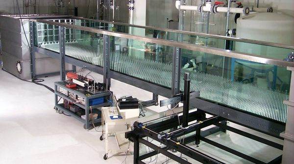
Re-circulating Water Channel
Coanda’s re-circulating water channel, shown above, has a test section 1.5 m wide x 1 m deep x 10 m long and is driven by an 8.5 m3/min centrifugal pump with a variable speed drive. Extensive optical access is possible due to the glass bottom and sides and a minimal number of support braces. Flow depth is controlled by a hinged weir in the outlet plenum. Mounting points along the top, sides and bottom of the channel enable installation of measurement equipment and traversing systems.
Realistic turbulent boundary layers are a key component of accurate atmospheric dispersion simulations. The water channel inlet flow conditioning can be modified to accelerate the development of the desired velocity profile. With a 10 m channel length, the first 3-5 m of channel is available for boundary layer development, leaving sufficient downstream fetch for dispersion testing.
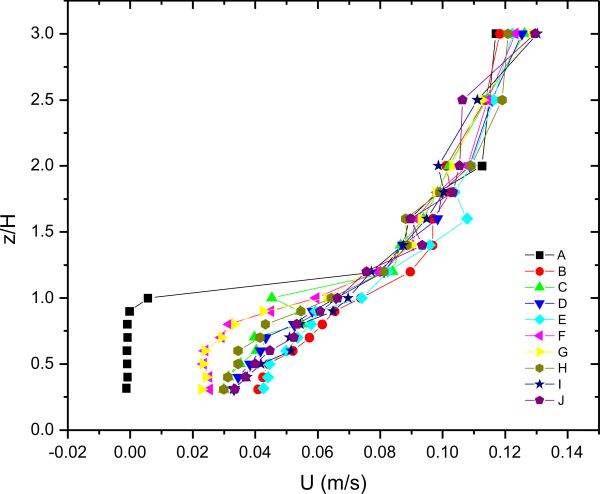
Velocity Measurements
Velocity field characterization is essential to understanding dispersion processes. Shown is a series of vertical velocity profiles within an obstacle array.Coanda has several types of instrumentation available for characterizing water channel boundary layer velocities as well as localized velocity distributions around obstacles in the flow:
- 4 beam 2-component TSI fiber optic laser doppler velocimeter (LDV) powered by an argon-ion laser
- 3-component Sontek acoustic doppler velocimeter
- Hot-film anemometer
Scalar Dispersion Measurements
The primary scalar measurement technique is laser induced fluorescence (LIF). Coanda has several digital cameras with a range of capabilities:
- 8 -12 bit resolution (256 to 4096 grey levels)
- 42 megapixel resolution maximum
- Linescan cameras with sampling rates of up to 4000 Hz
- 24-bit color digital still and video cameras
Illumination is provided by two 10 watt argon-ion lasers with fiber optic sheets or beam lighting systems.
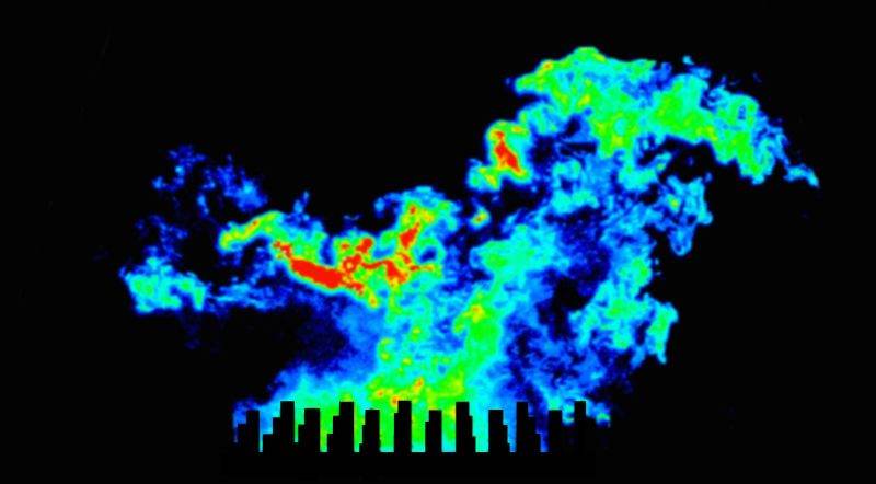
Image processing and analysis of dispersion images is performed with custom software developed by Coanda. This software is continually modified and improved to meet specific client requirements. Shown is a 2D image that shows an instantaneous false colored sample of the plume structure (roughness tabs are visible at the bottom of the image).
Other scalar tracer measurements are possible using a Coanda designed and manufactured multi-channel conductivity probe system to measure salt water/fresh water mixing or a multi-channel thermocouple system to measure thermal plumes. These techniques are advantageous in situations where optical access is limited.
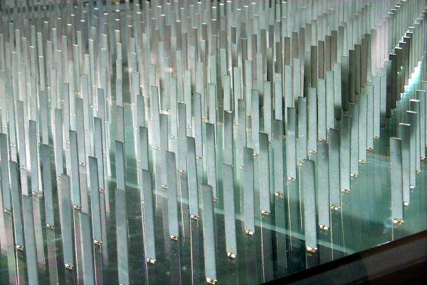
Surface Roughness and Obstacle Arrays
Surface roughness and obstacle arrays are easily installed on acrylic panels placed on the bottom of the water channel. Clear acrylic panels may be used if optical access from below is required. Obstacles may be constructed of virtually any material that does not corrode or dissolve in water. Coanda has performed many experiments with a variety of obstacles including stainless steel tabs, machined aluminum blocks, expanded metal surface roughness and Lego(TM) blocks. Where optical access through obstacles is necessary, clear, thin-walled acrylic obstacles have been used with great success.
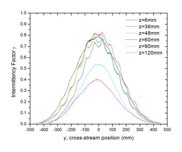
Such a sample obstacle array configuration is shown along with the data from a series of linescan dispersion measurements. The effect of the obstacles are clearly seen in the intermittency factor profiles across the plume (intermittency factor g is defined as the probability of observing a measurable concentration). Few other experimental techniques are able to resolve this level of detail in a dispersing plume.