CFD Modeling Pulp Digesters
Posted on March 16, 2023 Computational Fluid Dynamics Pulp & Paper

This post was originally published in two parts which have been combined below.
Part 1
The pulping process is the conversion of wood chips into separate fibres that can be used in various applications from paper production to hygiene products. The most popular chemical pulping process is Kraft pulping—where sodium hydrochloride and sodium sulphide are used to dissolve the lignin that binds fibres together in a piece of wood. The main component of the Kraft pulping mill is a digester: the place where chemical reactions occur to remove lignin from wood chips and to release fibres.
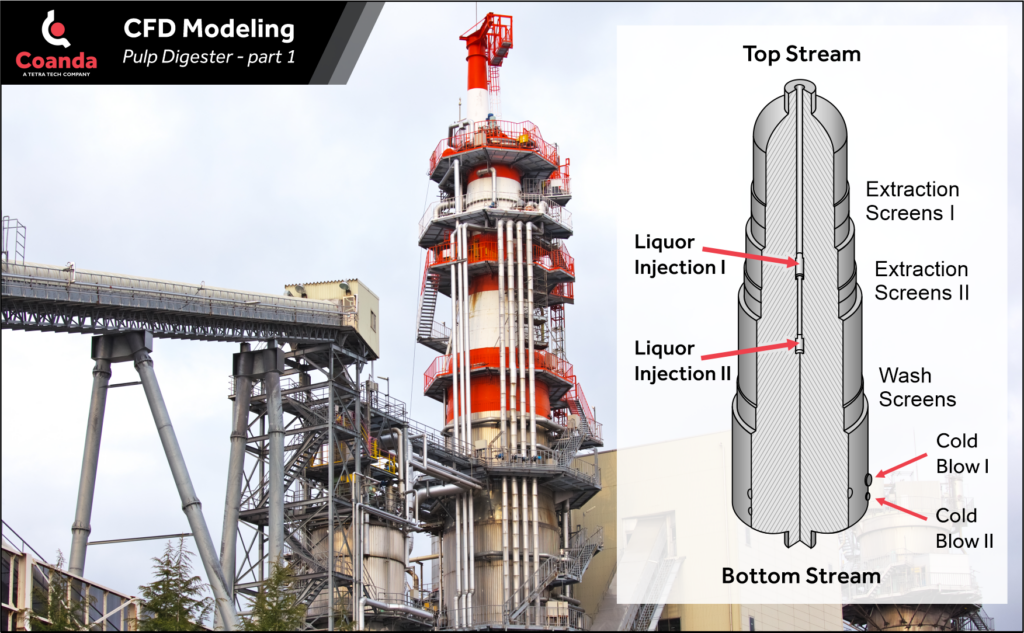
A continuous digester takes a steady inflow of wood chips and constantly blows out fibres. As shown in this schematic figure, the continuous digester is an upright cylindrical vessel with its diameter decreasing stepwise from bottom to top. At its centre is a concentric pipe that supplies a chemical solution, called liquor, for injection at several locations. After being loaded from the top, the heated wood chips and liquor start moving downwards. As the chip mass progresses downward through the digester, delignification reactions take place in which lignin is removed from the chips and dissolved into the liquid. At the bottom of the digester the chips, now with a significantly reduced lignin fraction, are taken out of the digester to be separated into wood fibres. Several injection and extraction areas of liquor are located along the digester height on the centre pipe and the outer wall, respectively.
Our next post will describe the modeling of the digester and present some results which provide insight into the operational details.
Part 2
As discussed in the previous post, the main component of the Kraft pulping mill is the digester, which represents a significant capital investment for mills. Thus, there has been considerable interest in modeling the digester process to optimise its design and operation. Numerical methods provide the ability to investigate parts of the process that otherwise are concealed from direct observations or even to sophisticated measurement techniques. Historically, digester modeling has been conducted from two perspectives: chemical processes and flow dynamics. While many useful conclusions can be gained by limiting the model to either the chemistry or to the fluid flow, the coupling between them is very important and affects the performance of the reactor.
We developed a mathematical model of the reacting multiphase flow in the pulp digester. The model considers wood chips—which contain lignin, carbohydrates, and trapped liquid—dispersed in free liquid, which itself is a mixture of chemicals and dissolved material.
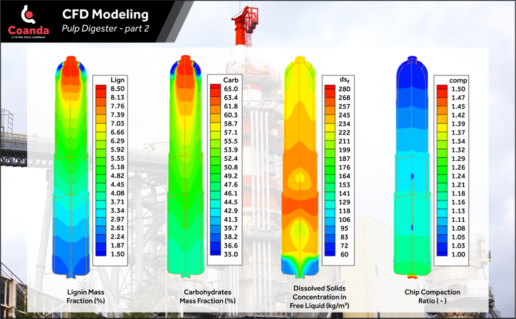
The modeling results provide insight into the digester operation. The transformation of the solid material in the digester is shown using contour plots for lignin and carbohydrate fractions. In the digester, most of the remaining lignin reacts with the alkali and dissolves into solution. Contours of the lignin mass fraction show the reaction actively starting in the upper section of the digester while the delignification rate slows as the chips steadily proceed towards the bottom. Some amount of carbohydrate is dissolved as well. The influence of buoyancy is clearly seen in the contours of the compaction ratio of the chip mass. Since the chip density is slightly larger than that of the free liquid, the compaction grows as the chip mass flows down the digester. The overall growth is about 30% before the chips are squeezed into the exit. Compaction is quite uniform across the digester, except in areas close to the injections, where a significant drop of the compaction value is observed in the immediate vicinity of the first and second injection areas.