CFD and Physical Modeling of Water Intakes
Posted on April 27, 2025 Computational Fluid Dynamics Water

The intent of the ANSI/HI 9.8 Hydraulic Institute Standard is to provide designers of pumping facilities a foundation upon which to develop functional and economical pumping facility designs. The Standard also endeavors to increase the understanding of pump intake physics and establishes firm design requirements. One of those requirements for rectangular intakes is that a physical model study is required for pumping stations with a total flow greater than 100,000 GPM or 40,000 GPM per pump.
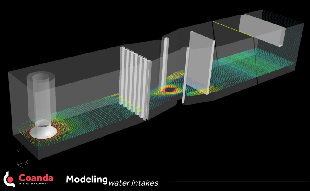
A detailed fluid dynamics study of a large pump house intake was carried out using computational fluid dynamic (CFD) simulations and experimental testing of a 1:12 scale physical model, as the flow per pump was greater than 40,000 GPM. First, a 3D CFD model of the initial Pump House intake design was created to determine the velocities near the pump intakes for minimum and normal liquid levels at maximum flow. From the CFD model, it was determined that a baffle structure should be installed some distance downstream of the traveling inlet screen to prevent large scale separation in the intake bay and significant inlet swirl at the pump suction bell.
Then, to completely satisfy the physical model objectives outlined in the Hydraulic Institute Standard ANSI/HI 9.8, a 1:12 scale model was built to determine free and sub-surface vortices as well as swirl and unsteadiness in the pump suction bell. Video recordings of swirl meter operation and dye injection at various locations were made, and time-averaged velocities were measured using non-intrusive LDV (Laser Doppler Velocimetry) across the throat of the suction bell. The experiments indicated that all acceptance criteria required by ANSI/HI 9.8-1998 were met by implementing the baffle structure originally modeled with CFD.