CFD Application for Wastewater Treatment Plants (WWTP)
Posted on June 22, 2022 Computational Fluid Dynamics Water

In the initial design of new wastewater treatment facilities or the expansion of existing ones, CFD is of particular benefit as it can quickly and accurately predict free surface flows through basins and influent/discharge structures. There are many instances in WWTP equipment that involve geometry of sufficient complexity for which a basic hydraulic analysis does not accurately account for flow non-uniformities or losses through more complex openings and screens. In these instances, CFD simulations provide high-resolution details of the flow and how it will affect the intended process—almost completely de-risking the design before it is implemented.
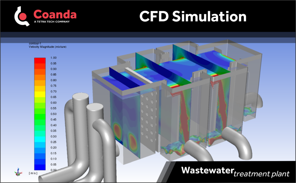
An example where CFD was of particular benefit involved the design a new influent distribution box in a WWTP which required two large pipe feed lines to be connected in a single structure to feed five clarifiers via Cipolletti weirs. Because the required footprint of the distribution box was relatively small, and the feed pipes could only be located in one particular orientation, the high momentum inlet jets from the feed pipes caused recirculating flow and large variations in the water free surface level within the distribution box. This uneven water surface level resulted in significant maldistribution of flow over the five weirs.
To combat the high momentum inlet jets, a concrete baffle wall with circular perforations was sized and located near the inlets of the distribution box. This new design was modeled using a CFD simulation of free surface water flow and the results indicated that the baffle wall essentially eliminated the uneven water surface level in the vicinity of the weirs by breaking up the momentum of the two large inlet jets. Thus an influent distribution structure with very tight spatial constraints, and fixed inflow and outflow locations, was designed and modeled with CFD to successfully distribute flow to multiple locations in a WWTP.