Torque Cells
Posted on October 25, 2022 Instrumentation & Equipment Design
A reaction torque cell supporting a motor can provide less noisy torque data more cost-effectively than a rotating cell. We’ll examine the internal construction and a subtle mechanism for spurious signals.
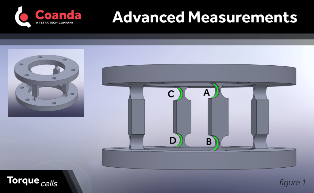
More sensitive, lower-range cells typically have four legs separating the flanges, which are machined thin where they contact the flanges. Four of these thinned sections are instrumented with strain gauges, as shown in the first figure.

The strain gauges are wired together such that the signal produced is A + D – B – C.
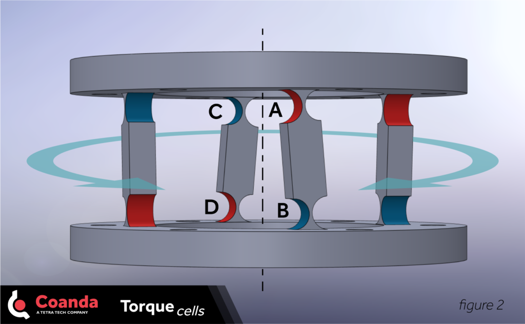
When the torque cell is torqued about the measurement axis, A and D are stretched (+) and B and C are compressed (-). As wired, each strain gauge contributes to a positive signal (second figure).

Think about the strain on the four gauges when off-axis torque or forces are applied. In each case, the contributions from the gauges cancel out. The torque cell only measures torque on the correct axis and ignores the rest.
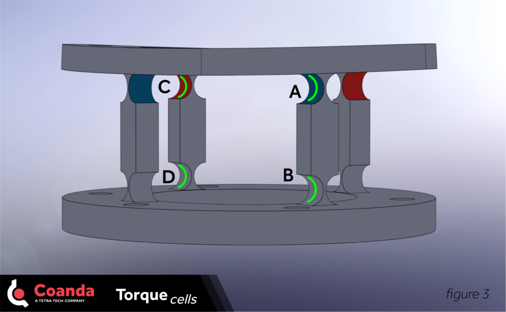
The immunity to non-torsional forces or off-axis torque falls apart if either of the surfaces the torque cell is bolted to get distorted. Consider a taco-shell distortion of the upper flange, clocked at 45° to the legs, as shown in the third figure.

Here C stretched (+), A is compressed (-) and B and D are unaffected. Nothing cancels and A + D – B – C is a negative signal. In situations where the torque mounts directly to machinery that distorts even slightly during operation, such as a gearbox with normal manufacturing tolerances, this mechanism will produce negative signals when the distortion is closer to 45° (or equivalently 225°) and positive signals when closer to 135° (or 315°). This creates two periods in the signal for one cycle of the distortion, which is a great clue that this mechanism is at play.


