Combustion Aerodynamics
Posted on February 16, 2017 Nozzles Jets Sprays Physical Modeling
The mixing of air and fuel in a combustion process, along with the efficient transport and/or propagation of heat to the desired location can affect the overall performance of a combustion related system. At Coanda these problems can be assessed using our analytical, physical and computational (CFD) modelling capabilities to evaluate and optimize the combustion process in your industrial application.
Introduction
Combustion, the reaction of a fuel with an oxidant, provides heat and energy in a wide variety of industrial and commercial processes. In a majority of applications there are two main aspects to the combustion process: the stable combustion of the fuel and the transfer of the heat generated to the system. The performance of both of these processes is dominated by the aerodynamics of the burner system and the aerodynamics of the process system. Understanding and optimizing system aerodynamics is an essential step in any combustion process.
Combustion Fundamentals
There are some basic concepts that can be found in any industrial combustion process. The flame, the region where the chemical reaction and heat release is taking place, is stabilized at a location where conditions are within certain limits. The flame can be either premixed, where the fuel and oxidant are mixed before entering the reaction zone, or non-premixed where mixing takes place in the reaction zone. The flame can also be either laminar or turbulent which better characterizes the type of mixing that is occurring rather than just the speed of the gas field. The difference in flame characteristics under different mixing regimes is shown below.
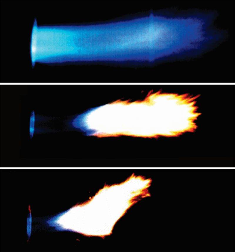
Lean, good, and poor combustion performance
Flame Stabilization
To stabilize a flame the mixing conditions must be optimal. The mixture must be within the stoichiometric limits of the fuel, there must be an ignition source and the velocity of the flow field needs to be lower than the flame speed (the maximum velocity that a flame front can propagate through a homogeneous mix of fuel and oxidant). Flame holders are often used to meet these requirements. This can be the lip of the feed nozzle if the jet exiting the nozzle is at a lower speed than the fuel’s flame speed. More often it is an object placed in the jet flame which creates a wake and subsequent recirculation zone where the flame can stabilize. This type of flame holder is also a hot source of ignition however these devices can deteriorate with time.
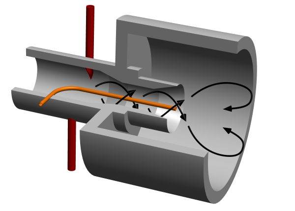
Aerodynamic stabilization is preferential over a physical flame holder. The aerodynamics of the flow is configured such that the conditions are conducive for combustion at a set location in the flow. This can take the form of a recirculation zone formed by swirl, a contoured expansion or a combination of both. An example of this type of burner flow is shown above. Practically, the recirculation zone holds the flame root by generating a significant reverse flow, drawing hot flame products toward the nozzle without introducing an object into the flame. This flow however requires careful design of flow conditions, flow rates, burner position and burner geometry.
Process Aerodynamics
Transport of heat and energy from the combustion process is a significant part of any industrial application of combustion. It can take the form of either convective or radiant heat transfer. In designing the flow characteristics of the flame and the overall system, attention must be paid to the requirements of the industrial process itself. The process may require a clean source of heat, so convective heat transfer is used with a non-soot generating flame, i.e. a pre-mixed flame. If rapid temperature rise is required, impingement of a high temperature flame can be used. Alternatively, if high temperature and high heat transfer is require and the process is detrimentally affected by the oxidizing atmosphere of the flame, a highly radiant flame is needed for maximum heat transfer and the aerodynamics of the process chamber are designed such that the flame does not impinge on the process feed.
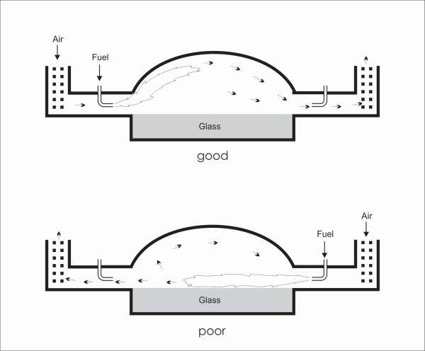
An example of the importance of understanding and optimizing the process system aerodynamics is shown above. The schematic shows a cross-sectional view of a furnace used in the manufacturing of glass. Several of these firing ports would be coupled together (out of plane) to form the whole glass tank furnace. These firing ports cycle in configuration from one side to the other. Air flows into the system over refractory which pre-heats the air allowing for heat recovery and helps stabilize the flame. With good aerodynamics, the luminous flame impinges on the roof allowing heat to be re-radiated into the glass pool. Exhaust gases heat the refractory in the outlet port. Poor aerodynamics can lead to flame impingement onto the glass pool. Any contaminates will affect the quality of the glass. The aerodynamics of the system change with time as the inlet refractory cools and this is the main parameter that sets the time of firing cycles.
Combustion Optimization
There are many different applications of combustion in industry. Requirements to use different fuels, produce different temperatures under different conditions and use different heat transfer modes result in an endless variety of flames. Changing one variable can have significant consequences on the performance of the flame and the overall process.
There are many different criteria that can be used to optimize an industrial combustion process. The obvious one is the amount of fuel burnt or consumed for a given process. Often, only a small improvement in combustion efficiency or heat transfer efficiency can lead to direct fuel savings. Other criteria that can be used include an increase in product throughput for a given fuel usage, stable operation of the combustion process, longer times between shutdowns for major overhaul, increase in product quality, reduced number of defective products and an overall reduction in process emissions and pollution.
Modelling Aerodynamics at Coanda
Coanda has developed significant capability in the analytical, physical and computational (CFD) modelling of fluid systems. Mixing fields can be investigated using Coanda’s planar laser-induced florescence (PLIF) system. While velocity measurements can be made using Coanda’s commercial laser Doppler velocimetry (LDV) system. Along with modeling and measurement, Coanda has extensive capability to design and build scaled models of burners and process systems.
With this combination of modeling, model construction and measurement and Coanda’s strong background in researching mixing problems, we can evaluate your current situation and offer design improvements.